
The Orion Program conducted rigorous testing of the spacecraft, from element-level testing with test articles for the crew module, service module, LAS, parachute system, and other supporting systems—including both flight tests and ground tests—to integrated testing of the full spacecraft that have flown on Artemis missions.

Heat Shield Testing
Artemis I FindingsAfter Orion’s return to Earth at the end of the Artemis I mission, unexpected char loss was observed across the spacecraft’s heat shield. Soon after NASA engineers discovered this condition, the agency began an extensive investigation process, which included a multi-disciplinary team of experts in thermal protection systems, aerothermodynamics, thermal testing and analysis, stress analysis, material test and analysis, and many other related technical areas. NASA’s Engineering and Safety Center was also engaged to provide technical expertise including nondestructive evaluation, thermal and structural analysis, fault tree analysis, and other testing support.
The Artemis I heat shield was heavily instrumented for flight with pressure sensors, strain gauges, and thermocouples at varying ablative material depths. Data from these instruments augmented analysis of physical samples, allowing the team to validate computer models, create environmental reconstructions, provide internal temperature profiles, and give insight into the timing of the char loss.
Approximately 200 Avcoat samples were removed from the Artemis I heat shield at NASA’s Marshall Space Flight Center in Alabama for analysis and inspection. The team performed non-destructive evaluation to “see” inside the heat shield.
Extensive analysis, including 121 tests at unique facilities across the country, determined the heat shield on Artemis I did not allow for enough of the gases generated inside a material called Avcoat to escape, which caused some of the material to crack and break off. Avcoat is designed to wear away as it heats up and is a key material in the thermal protection system that guards Orion and its crew from the nearly 5,000 degrees Fahrenheit of temperatures that are generated when Orion returns from the Moon through Earth’s atmosphere. Although a crew was not inside Orion during Artemis I, data shows the temperature inside Orion remained comfortable and safe had crew been aboard.
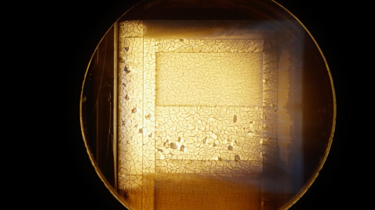
In the spring of 2024, NASA stood up an independent review team to conduct an extensive review of the agency’s investigation process, findings, and results. The review occurred over a three-month period to assess the heat shield’s post-flight condition, entry environment data, ablator thermal response, and NASA’s investigation progress. The review team agreed with NASA’s findings on the technical cause of the physical behavior of the heat shield.
Engineers understand both the material phenomenon and the environment the materials interact with during entry. By changing the material or the environment, they can predict how the spacecraft will respond. Extensive data from the investigation gave engineers confidence that the heat shield for Artemis II can be used to safely fly the mission’s crew around the Moon and back. NASA modified the Artemis II trajectory by shortening how far Orion can fly between when it enters Earth’s atmosphere and splashes down in the Pacific Ocean. This will limit how long Orion spends in the temperature range in which the Artemis I heat shield phenomenon occurred.
Knowing that permeability of Avcoat is a key parameter to avoid or minimize char loss, NASA has the right information to assure crew safety and improve performance of future Artemis heat shields. Engineers already are assembling and integrating the Orion spacecraft for Artemis III based on lessons learned from Artemis I and implementing enhancements to how heat shields for crewed returns from lunar landing missions are manufactured to achieve uniformity and consistent permeability.
Exploration Flight Test-1 FindingsFollowing Exploration Flight Test-1, the Orion heat shield was redesigned from a single-piece system to individual blocks of material. Before the time-saving block system was used, a fiberglass-phenolic honeycomb structure was bonded to the structure’s skin. Then each of the 320,000 tiny honeycomb cells were individually filled with Avcoat by hand, inspected by X-ray, cured in a large oven, and robotically machined to meet precise thickness requirements.
The new design introduced several considerations that prompted further testing for risk reduction. Engineers performed more than 30 tests across the United States on the new design to investigate the effects of the block structure that could disrupt the smooth airflow and cause localized heating spots. Understanding both effects confirmed that the heat shield will thermally protect the astronauts during entry into Earth’s atmosphere.
Teams tested the Avcoat material at NASA’s Ames Research Center’s Arc Jet Complex and at NASA’s Johnson Space Center’s Atmospheric Reentry Materials and Structures Evaluation Facility. Teams also performed thermal testing at Johnson’s Radiant Heat Test Facility. During these tests, the Avcoat surface reached temperatures of over 3,000 degrees Fahrenheit (1,649 degrees Celsius). Heat shield testing also took place at NASA’s Langley Research Center with a 6-inch Orion heat shield model in the 20-inch Mach 6 wind tunnel. The model was machined to represent small-scale features, including the patterns expected as the heat shield ablates during return to Earth.
Artemis I Orion Environmental Test Article Campaign
Following the Artemis I mission, Orion’s crew module — now known as the Orion Environmental Test Article — returned to NASA’s Neil Armstrong Test Facility in Sandusky, Ohio, in January 2024 and completed an 11-month test campaign. The campaign was necessary to ensure Orion is ready to protect the crew if an emergency occurs during Artemis II’s launch.
Engineers and technicians from NASA and Lockheed Martin subjected the test article to the extreme conditions Orion may experience in a launch abort scenario. Experts conducted tests that simulated the noise levels of an abort during launch in addition to the electromagnetic effects of lightning strikes. The test campaign also jettisoned the test article’s docking module and parachute covers, as well as the crew module uprighting system, which consists of five airbags on top of the spacecraft that inflate upon splashdown.
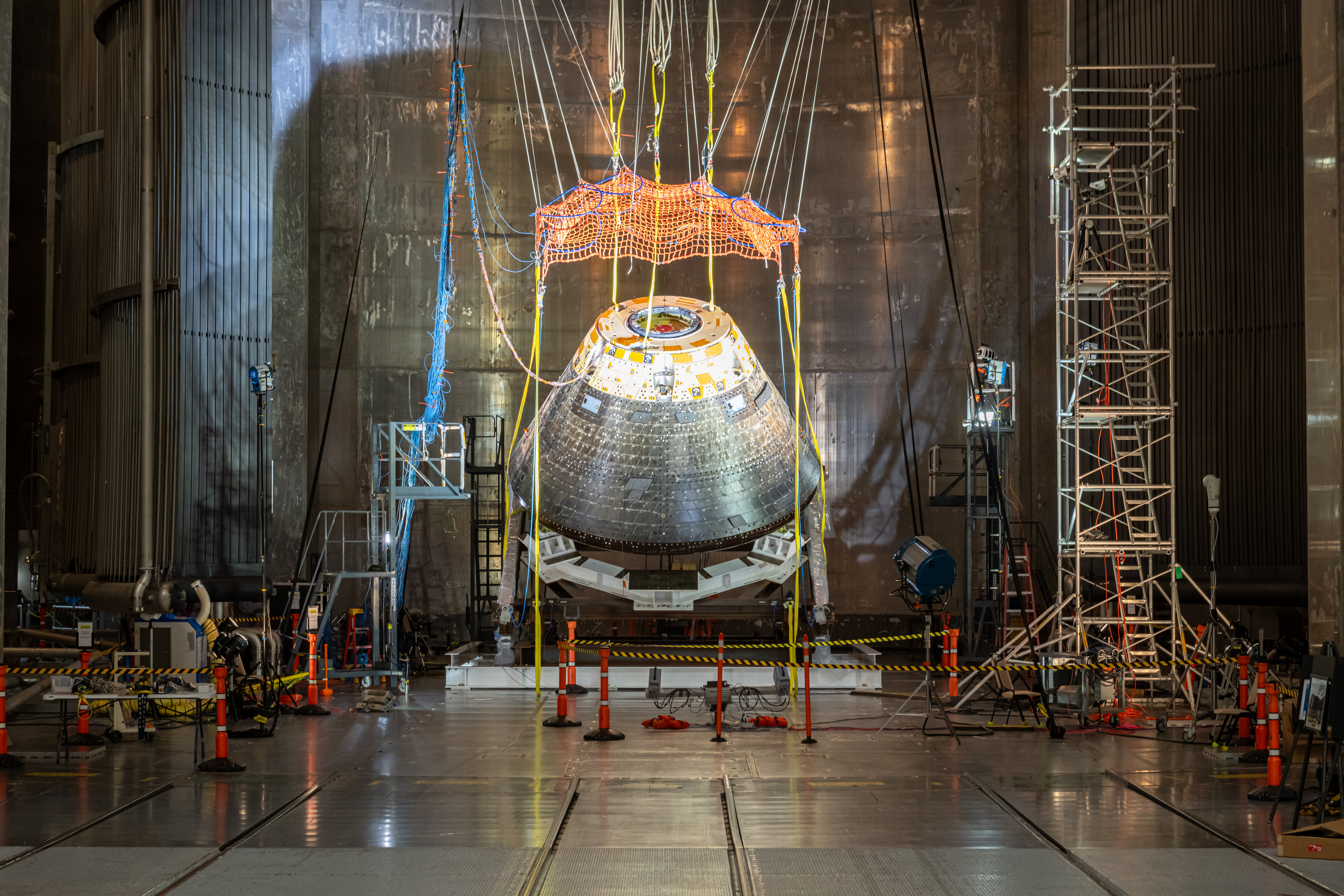
After completing testing at Armstrong Test Facility, the ETA was shipped to Kennedy Space Center, where the team performed final functional testing of Orion’s propulsion and environmental control and life support systems inside the center’s Multi-Payload Processing Facility.
Data from the testing matched engineers’ prediction models, and Orion operated as expected after being subjected to nominal and launch abort acoustic levels. The critical testing helped to ensured that the Artemis II spacecraft can fly crew safely and successfully.
Pre-Flight Testing
Acceptance Testing
At Kennedy, the Artemis II Orion crew and service modules underwent functional and performance testing in the high bay of the Neil A. Armstrong Operations and Checkout Building to ensure quality assurance before ground processing and integration with the SLS rocket in the Vehicle Assembly Building.
Proof Pressure TestingTo ensure that the Artemis II spacecraft could withstand the rigors of spaceflight, engineers completed a series of tests on the pressure vessel. In a test stand inside the proof pressure cell, technicians attached hundreds of strain gauges to the interior and exterior surfaces of the structure. The strain gauges measured the strength of the welds as the pressure vessel was pressurized at incremental steps over two days to reach the maximum pressure it is expected to encounter during flight. The tests confirmed that the weld points would endure the extreme forces during the launch, in-space, entry into Earth’s atmosphere, and landing phases on Artemis missions.
Crew Module and Service Module Functional and Performance TestingThe Artemis II Orion crew module underwent initial power-on events. This included the first time the vehicle management computers and the power and data units were installed on the crew module, loaded with flight software, and tested. These tests verified the health and status of Orion’s core computers and power and data units; they also ensured that the systems were able to communicate precisely with one another to accurately route power and commands throughout the spacecraft.
The Artemis II Orion service module also separately underwent initial power-on tests. The tests allowed technicians to check that all cables were properly connected, and data was transferred at the speeds required by the spacecraft and to accommodate power distribution across the module.
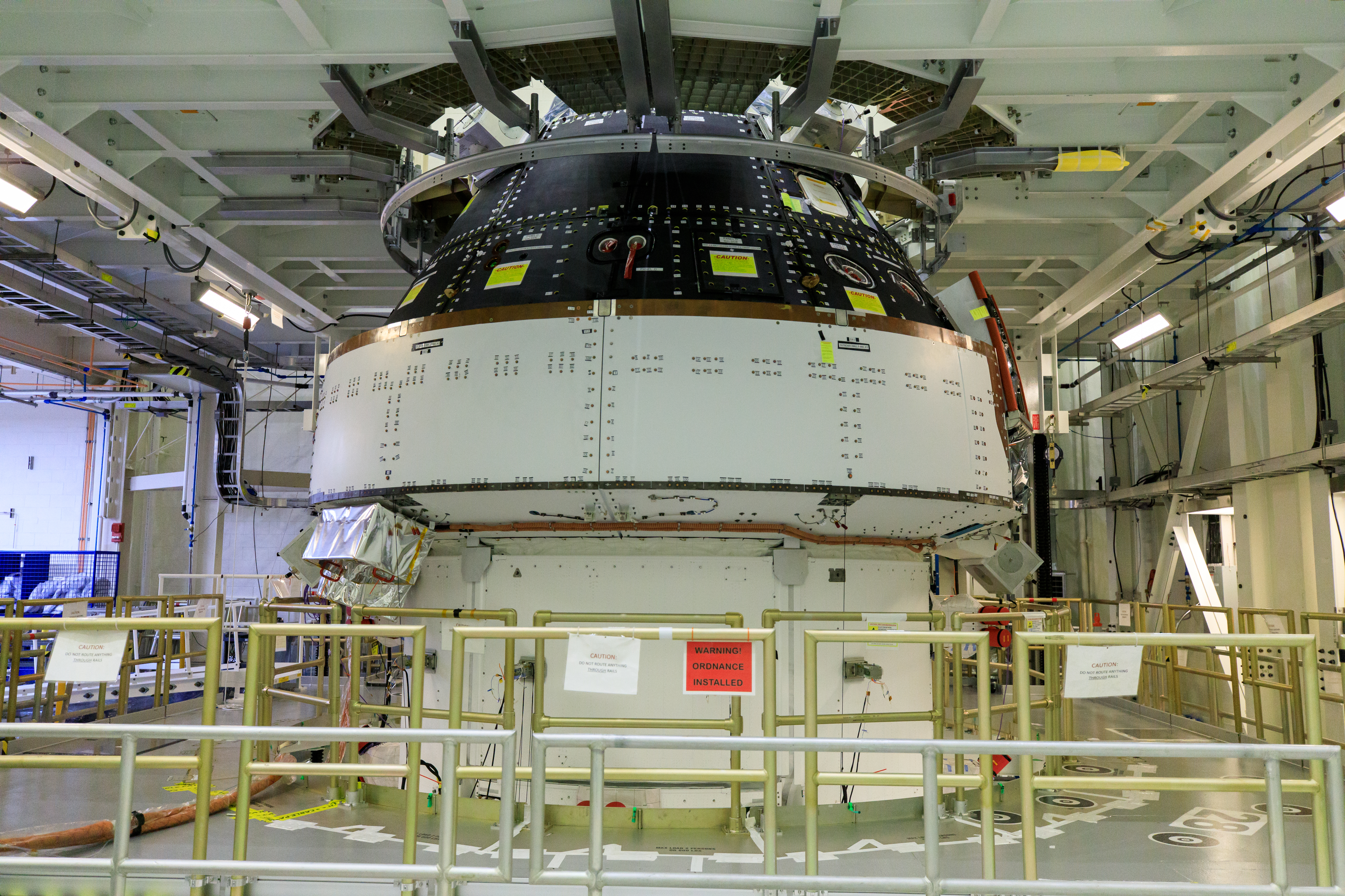
After initial power-on, the Orion crew module and service module underwent separate functional testing, which ensured that each of the module’s systems powered on and functioned as designed. After engineers completed functional testing, teams conducted separate performance testing of the crew module and service module. This testing verified that each module’s systems not only powered on but functioned within the correct parameters. Performance testing also took place after the two modules were joined. For Artemis II, this included additional testing required to demonstrate that life support systems not flown on Artemis I can function and perform as expected.
Environmental TestingEnvironmental testing simulates environments the spacecraft will experience through launch, travel in deep space, and recovery. It also evaluates the spacecraft’s structure and systems in those conditions. Before joining the crew module and service module for the Artemis II mission at Kennedy, engineers conducted acoustic and thermal-cycle testing for each module separately in the high bay of the Operations and Checkout Building.
Direct Field Acoustic TestingDuring this testing, the crew module or service module was surrounded with speakers and exposed to maximum acoustic levels that Orion will experience in space. Engineers secured the module inside a test cell and then attached microphones, strain gauges, and accelerometers. The module was blasted with extreme vibrations and acoustic levels up to 141 decibels — as loud as a jet engine during takeoff — to ensure that the spacecraft and its systems could withstand the noise expected during launch.
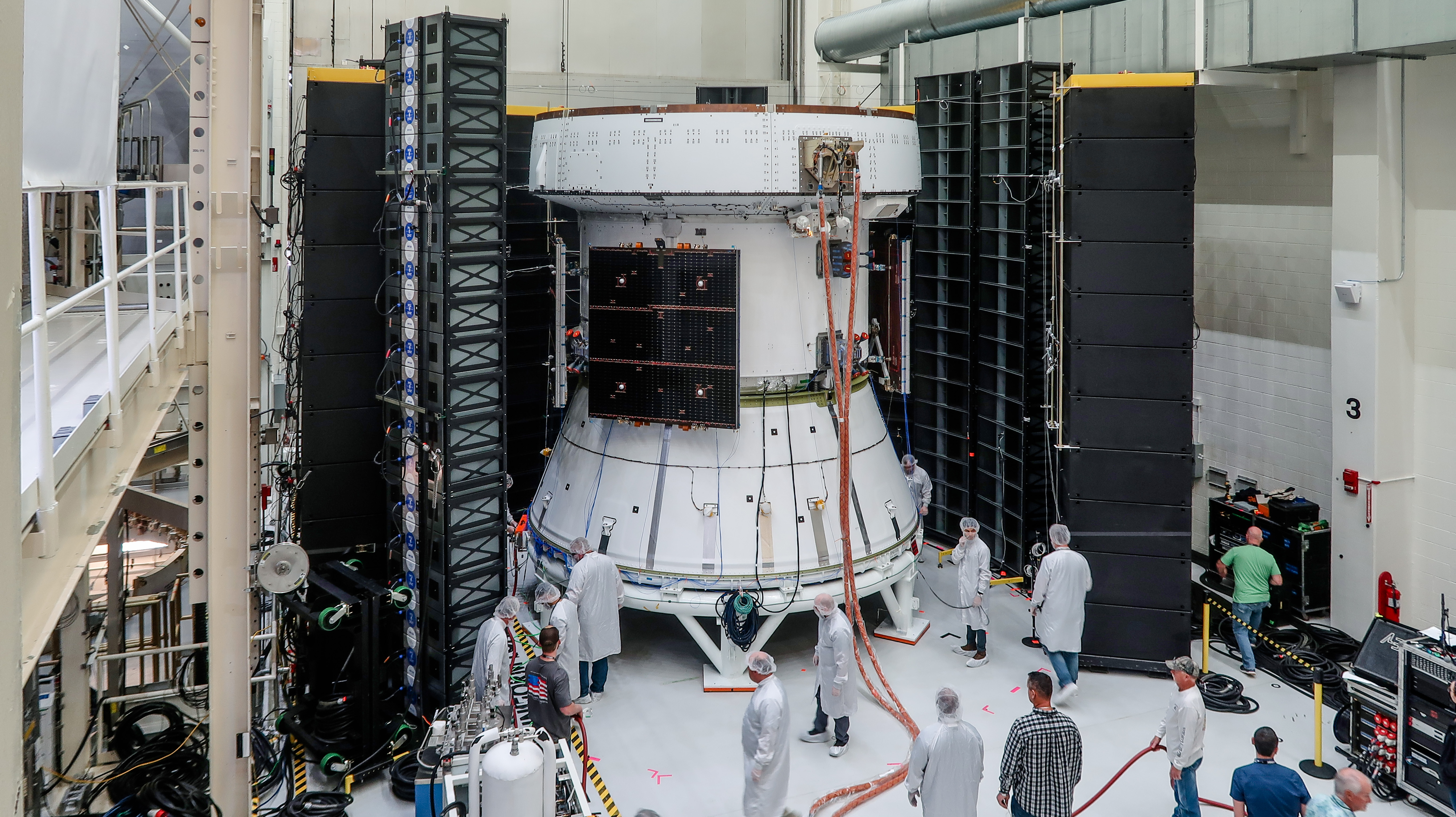
Inside a specially constructed thermal cycle chamber, teams rapidly cycled the crew or service module between hot and cold temperatures over several days to thermally stress the hardware and ensure the workmanship of its hardware and subsystem operations. The cycle of temperatures for the initial thermal test ranged from 29 to 129 degrees Fahrenheit (-1.6 to 54 degrees Celsius) during 105 hours of testing.
Altitude Chamber TestingAfter engineers at Kennedy completed testing on the Artemis II crew and service modules individually, they were moved to the Final Assembly and System Testing cell, where they were integrated and put through their final system tests prior to two rounds of rigorous, simulated in-space environmental testing inside the west altitude chamber in the Operations and Checkout Building high bay.
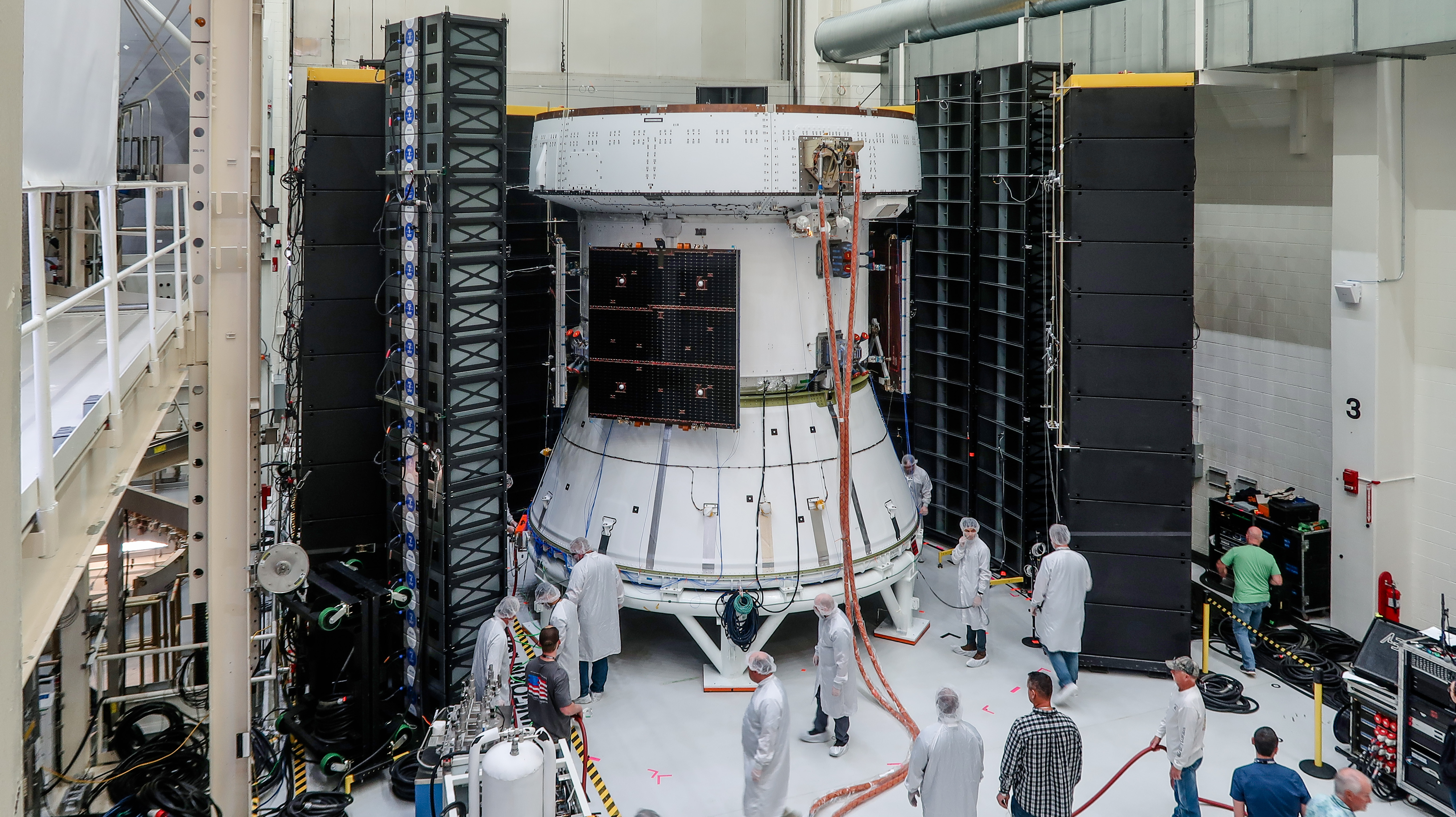
To prepare, the west altitude chamber was upgraded to test the spacecraft in a vacuum environment that simulates an altitude of up to 250,000 feet. These upgrades reactivated altitude chamber testing capabilities for the Orion spacecraft at Kennedy. Previous vacuum testing on the Orion spacecraft for Artemis I took place at NASA’s Glenn Research Center in Cleveland. Teams also installed a 30-ton crane in the Operations and Checkout Building to lift and lower the Orion crew and service module stack into the chamber, lift and lower the chamber’s lid, and move the spacecraft across the high bay.
Originally used to test environmental and life support systems on the lunar and command modules during the Apollo program, the interior of the two altitude chambers in the Operations and Checkout Building measure 33 feet in diameter and 44 feet high and were designed to simulate the vacuum equivalent of up to 200,000 feet — a deep space environment. Both chambers were rated for astronaut crews to operate flight systems during tests.
- Integrated Spacecraft Electromagnetic Interference/Compatibility Testing: During the first round of altitude chamber testing in April 2024, the team checked out Orion’s electromagnetic interference and compatibility and verified that systems performed as they would during the mission. All electronic components have an electromagnetic field that can affect other electronics nearby. This testing ensured that the spacecraft’s electronics worked properly when operated at the same time, as well as when bombarded by external sources. The test campaign confirmed that the spacecraft’s systems performed as designed.
- Integrated Spacecraft Vacuum Chamber Testing: In July 2024, the Artemis II spacecraft was returned to the altitude chamber for another round of testing, simulating deep space vacuum conditions. The testing subjected the spacecraft to a near-vacuum environment by removing air, thus creating a space where the pressure is extremely low. This results in no atmosphere, similar to the one the spacecraft will experience during future lunar missions. In early November 2024, teams returned the Artemis II spacecraft to the altitude chamber for a second round of vacuum testing, which was focused on checking out environmental control and life support system components.
Following altitude chamber testing, Orion was returned to the Final Assembly and System Testing cell for a final round of testing and assembly that included end-to-end performance verification of the spacecraft’s subsystems, checking for leaks in the spacecraft’s propulsion systems, installing its solar array wings, performing spacecraft closeouts, and pressurizing a subset of its tanks in preparation for flight prior to rolling to the Multi-Payload Processing Facility (MPPF). There, Orion received servicing and crew equipment interface testing before being integrated with the rocket.
Flight Servicing and Integrated Testing
After the Orion crew and service module stack completes testing and assembly in the Operations and Checkout Building, the spacecraft is handed over to the Exploration Ground Systems team to be serviced for flight, integrated with its launch abort system, stacked on top of the SLS rocket in the Vehicle Assembly Building, and undergo final integrated testing before launch.
Multi-Payload Processing FacilityInside the Multi-Payload Processing Facility (MPPF), the spacecraft is fueled with hazardous propellants and other fluids it will need for the journey around the Moon, and undergoes various testing:
- Crew Module/Service Module Propulsion Servicing: Once inside the MPPF, teams begin with service module propellant servicing, filling the service module’s tanks with monomethylhydrazine (MMH) propellant, an oxidizer known as mixed oxides of nitrogen (MON)-3, and helium for pressurization. The teams then service the crew module propulsion system with hydrazine and helium for pressurization.
- Crew Module/Service Module Propulsion Servicing: Once inside the MPPF, teams begin with service module propellant servicing, filling the service module’s tanks with monomethylhydrazine (MMH) propellant, an oxidizer known as mixed oxides of nitrogen (MON)-3, and helium for pressurization. The teams then service the crew module propulsion system with hydrazine and helium for pressurization.
- Crew Module/Service Module Oxygen Servicing: Teams fill the crew module and service module oxygen tanks the crew will use to breathe. Oxygen tanks in the service module are used from launch up until the crew module separates from the service module for re-entry into Earth’s atmosphere. The crew module oxygen tanks are then used from separation until splashdown.
- Crew Module Ammonia Boiler Servicing and Test: Teams fill the crew module ammonia boiler tanks, then perform a functional test of the ammonia boiler to ensure it will function properly during ascent and entry. The ammonia boiler cools the vehicle during ascent and entry.
- Crew Suited and Crew Equipment Interface Testing: After the Artemis II spacecraft was serviced with its necessary commodities, the Artemis II crew entered their spacecraft for a multi-day training in July 2025. The crew boarded Orion for a suited crew test and crew equipment interface test, performing launch day and simulated orbital activities inside the spacecraft. Inside Orion, to replicate launch preparations, the crew performed communications checkouts and suit-leak checks. For the first time, the crew was connected to the spacecraft and its communications and life control systems, and all umbilicals were connected while the spacecraft operated on full power. Teams simulated several different ground and flight conditions to give the crew more experience managing them in real time. Some of the activities simulated scenarios where the crew was challenged to address potential issues while in space such as leaks and failure of the air revitalization system fan, which is needed to provide oxygen and remove carbon dioxide from the cabin. The test provides astronauts the ability to train on the actual hardware they will use during flight, allowing them and support teams the opportunity to familiarize themselves with the equipment in configurations very close to what will be experienced during flight. It also allows teams to verify compatibility between the equipment and systems with flight controller procedures, so they can make any final adjustments ahead of launch.
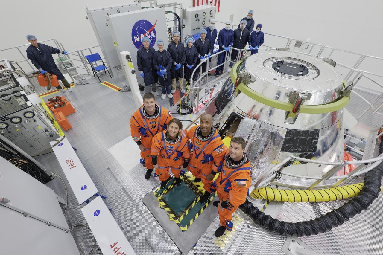
After fueling is completed in Kennedy’s Multi-Payload Processing Facility, the spacecraft is transferred to the center’s Launch Abort System Facility, where the launch abort system, or LAS, is integrated with the crew and service modules. Once the LAS tower and ogives are integrated with the spacecraft, various testing takes place:
- LAS and Crew Module Tandem Hatch Testing: After installation of the LAS ogives, the team performs functional testing of the LAS hatch in tandem with the crew module hatch to ensure that both hatches will open properly in an emergency egress situation.
- LAS Communications System Testing: The team conducts communications testing of the LAS S-Band antennas to verify that they can be used to transmit vehicle data from the crew module during launch and ascent.
- Vehicle Purge Leak Test: Purge leak testing identifies and verifies leakage areas of the LAS and crew and service modules, to ensure that purge operations will be able to keep the vehicle protected from the outside environment during transportation and while the spacecraft is out on the pad.
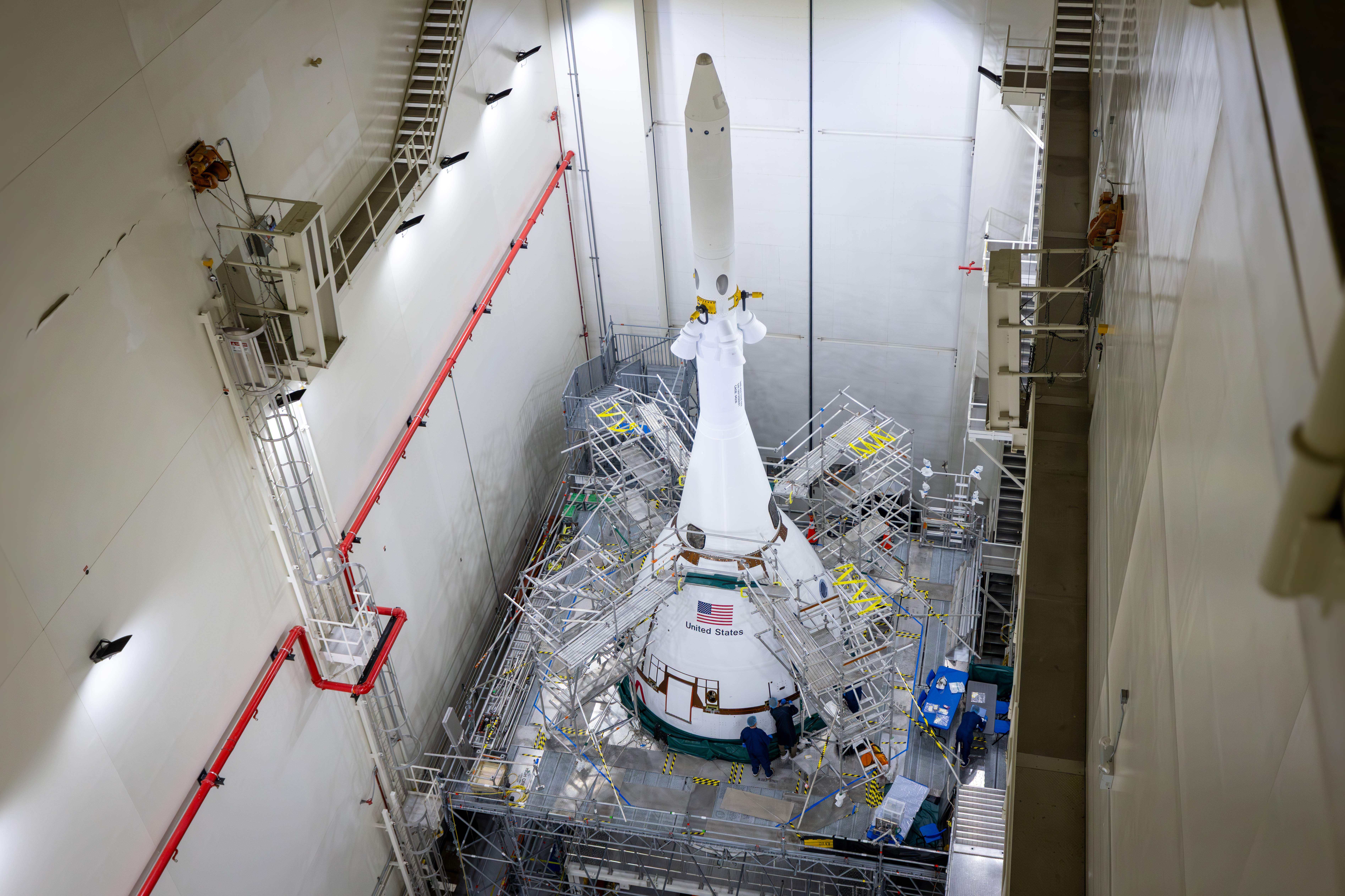
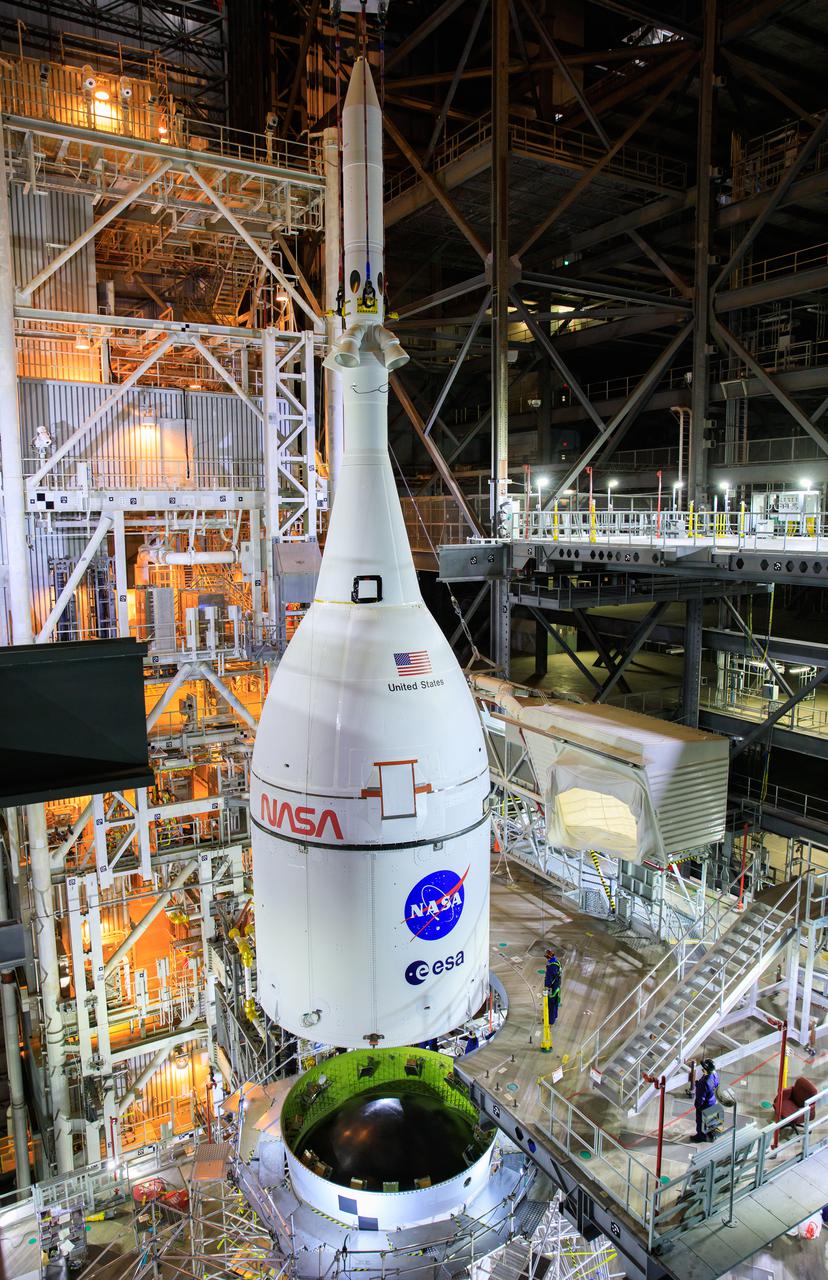
After the LAS is fully integrated and Launch Abort System Facility operations are complete, the full Orion stack leaves the building and moves to the Vehicle Assembly Building (VAB) for stacking on top of the SLS rocket. Once integrated with the SLS, Orion undergoes further servicing, testing, and closeout operations:
- Potable Water System Servicing: Once Orion is integrated with rocket in the VAB, the four potable water tanks in the service module are flushed and filled. This is done as close as possible to rollout to the launchpad for shelf-life purposes.
- Nitrogen System Servicing: Orion’s service module nitrogen tank is filled. This is performed after the potable water system servicing as the nitrogen is used for pressurizing the water tanks and for providing pressure control for the crew module.
- Countdown Demonstration Test (CDDT): Teams conduct a launch day demonstration with the Artemis II crew to test launch countdown procedures and make any final necessary adjustments ahead of launch. While SLS and Orion are in the VAB, the Artemis II crew depart their crew quarters after suiting up at the Neil A. Armstrong Operations and Checkout Building and drive to the VAB where they enter Orion like they will on launch day and practice getting strapped in.
- Final Closeouts Before Rollout: The team closes out all of Orion’s service panels and performs final stowage operations, before the entire SLS stack rolls out to Pad 39B.
Early Development and Testing
Launch Abort System Testing
Testing for Orion’s launch abort system included two major flight tests, along with hot fire testing for the individual motors.
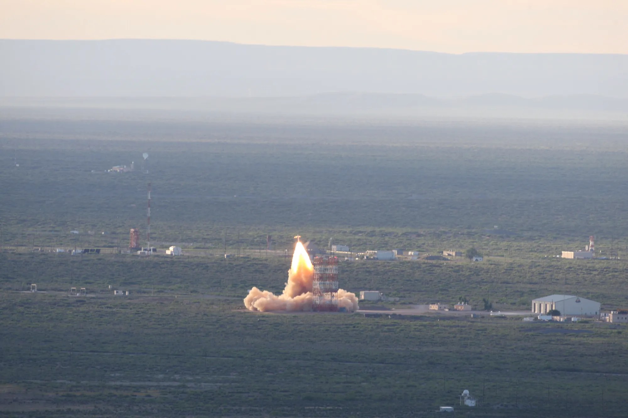
Pad Abort-1NASA’s Pad Abort-1 test was Orion’s first major flight test and the first fully integrated test of the LAS. The agency successfully launched a test version of the crew module and its launch abort stack on May 6, 2010, at the U.S. Army’s White Sands Missile Range near Las Cruces, New Mexico. The flight test demonstrated the capability of the LAS to propel the crew module to a safe distance during a ground-initiated abort on the launch pad.
The test lasted about 2.5 minutes from launch until the test version of the crew module touched down about a mile north of the launch pad. The crew module reached a speed of approximately 445 mph in the first three seconds, with a maximum velocity of 539 mph in its upward trajectory to about 1.2 miles high. The parachutes guided the crew module to touchdown at 16.2 mph.
Pad Abort-1 Testing
| Launch date | May 6, 2010 7:00 a.m. MDT |
| Launch site | U.S. Army’s White Sands Missile Range, New Mexico Launch Complex 32E |
| Duration | 2 min., 15 sec. |
| Distance | 6,900 ft. downrange |
| Altitude | 6,336 ft. |
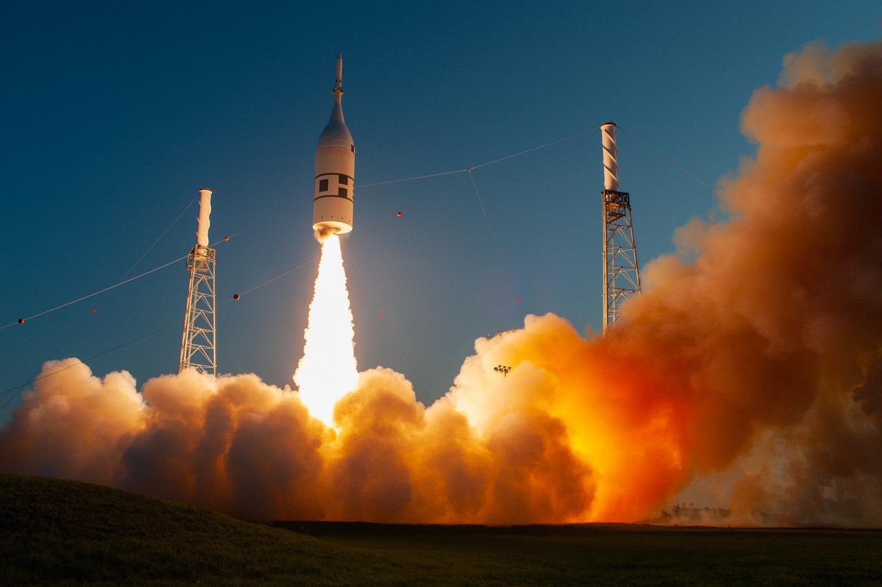
NASA conducted the second major flight test for the launch abort system, known as Ascent Abort-2, on July 2, 2019, to test the Orion LAS during ascent, which is when the spacecraft is expected to experience the greatest aerodynamic stress. Combined with subsystem qualification tests and the successful Pad Abort-1 test, this test resulted in a LAS that is certified to fly on the Artemis missions with astronauts aboard.
During the test, which lasted approximately three minutes, a booster provided by Northrop Grumman launched from Space Launch Complex 46 at Cape Canaveral Air Force Station in Florida. It carried a fully functional LAS and a test version of Orion to an altitude of nearly six miles at over 1,000 mph. At that point, the LAS’ powerful reverse-flow abort motor fired 400,000 pounds of thrust, propelling the Orion test article to a safe distance away from the rocket to splash down in the Atlantic Ocean. For cost-saving purposes, the test article was not equipped with parachutes, nor was the test capsule recovered from the ocean.
Ascent Abort-2 Testing
| Launch date | July 2, 2019 7:00 a.m. EDT |
| Launch site | Cape Canaveral Air Force Station, Florida, SLC-46 |
| Duration | 3 min., 13 sec. |
| Altitude | 31,000 ft. (at abort initiation), 55,000 ft. (Orion test vehicle maximum altitude) |
Engineers have completed final qualification testing for each of the LAS motors — the attitude control motor, jettison motor, and abort motor. These tests looked at the maximum high- and low-temperature conditions that a motor might see during a launch in Florida to provide the data on how the motor reacts under hot or cold stressing conditions.
Abort MotorDuring a series of static-fire tests in Promontory, Utah, the abort motor was secured to a vertical stand with its nozzles pointed skyward and fired for five seconds, producing exhaust flames up to 100 feet high and reaching approximately 400,000 pounds of thrust in one-eighth of a second—enough to lift 66 large SUVs—verifying it can ignite within milliseconds and perform under extreme conditions. The hot, cold, and ambient tests each confirmed the motor functioned as intended across the full range of temperatures encountered during launch operations. For the final test, the Orion program strategically incorporated a new EPDM rubber insulator material, which is bonded to the inside of the motor casing before the propellant is poured. Successful completion of this series officially qualified the LAS abort motor for crewed flight.
Abort Motor Testing
| Test | Test Date | Environmental Condition | Temperature |
| QM-1 | June 15, 2017 | Hot Condition | 100°F |
| QM-2 | Dec. 13, 2018 | Cold condition | 27°F |
| QM-3 | March 31, 2022 | Ambient condition (Motor with new insulation) |
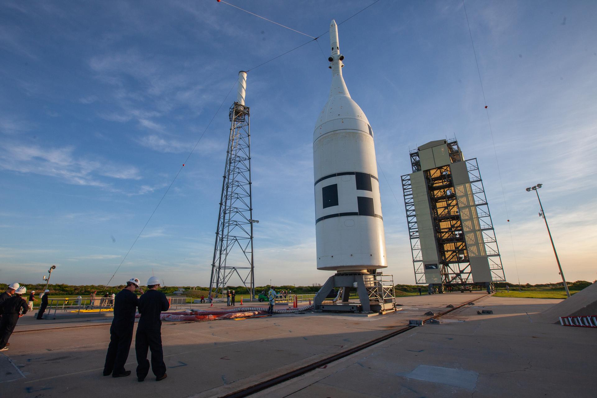
The attitude control motor has undergone three qualification tests in Elkton, Maryland. During each of the three 30-second hot fire tests, the motor’s eight high-pressure valves directed more than 7,000 pounds of thrust in multiple directions, proving the motor can provide enough force to orient Orion and its crew for a safe landing. The ambient, hot, and cold tests each confirmed the system performed as intended under the range of temperature conditions a motor might experience during a launch. During the cold test, the motor was ignited using one of two initiators and operated under simulated high-altitude vacuum conditions to demonstrate worst-case performance. Successful completion of all three tests confirmed the attitude control motor meets requirements for safe and reliable operation during crewed missions.
Attitude Control Motor Testing
| Test | Test Date | Environmental Condition | Temperature |
| QM-1 | March 20, 2019 | Ambient Condition | 70°F |
| QM-2 | Aug. 22, 2019 | Hot Condition | 94°F |
| QM-3 | Feb. 25, 2020 | Cold Condition | 30°F |

The jettison motor was tested by engineers at the U.S. Army Redstone Test Center on Redstone Arsenal in Huntsville, Alabama. Three 1.5‑second hot fire qualification tests demonstrated the jettison motor could successfully produce more than 40,000 pounds of thrust under the different conditions it might encounter during launch. The hot, cold, and ambient‑temperature tests each confirmed the system performed as intended across the full range of temperatures a motor might experience during a launch.
Aerojet Rocketdyne also completed a demonstration test on Aug. 28, 2019 with the first jettison motor that utilized Aerojet Rocketdyne’s Orange, Virginia, facility for propellant mixing and loading and motor final assembly. The Demonstration Motor-4, or DM-4 test, rounded out an extensive two-year transition effort that increased affordability and demonstrated that there was no loss of fidelity or quality in the transfer of the program from California to Virginia.
Jettison Motor Testing
| Test | Test Date | Environmental Condition | Temperature |
| QM-1 | March 20, 2019 | Ambient Condition | 70°F |
| QM-2 | August 22, 2019 | Hot Condition | 94°F |
| QM-3 | Feb. 25, 2020 | Cold Condition | 34°F |

European Service Module Propulsion Testing
Engineers used a replica of the service module’s propulsion subsystem, called the propulsion qualification module (PQM), for testing at NASA’s White Sands Test Facility. The data from these tests helped to certify the service module propulsion system for the Artemis I and II missions and beyond. The PQM was designed to verify the performance of the service module engines, propellant feed systems, and various other propulsion operations during expected and unexpected conditions. Testing of the PQM ensured that all engines and thrusters fired safely and accurately to prove that they would be reliable in getting the spacecraft where it needs to go during deep space exploration missions.
The PQM was equipped with a total of 21 engines: one U.S. Space Shuttle Orbital Maneuvering System (OMS) engine, eight auxiliary thrusters, and 12 smaller reaction control system thrusters produced by Airbus in Germany. The service module that will fly on Artemis missions has 33 engines in total, with double the amount of reaction control system thrusters included in the PQM. The full module was a roughly 15-foot cube made of stainless steel that provided the full components for testing the thrusters, fuel lines, and firing of Orion’s engines.
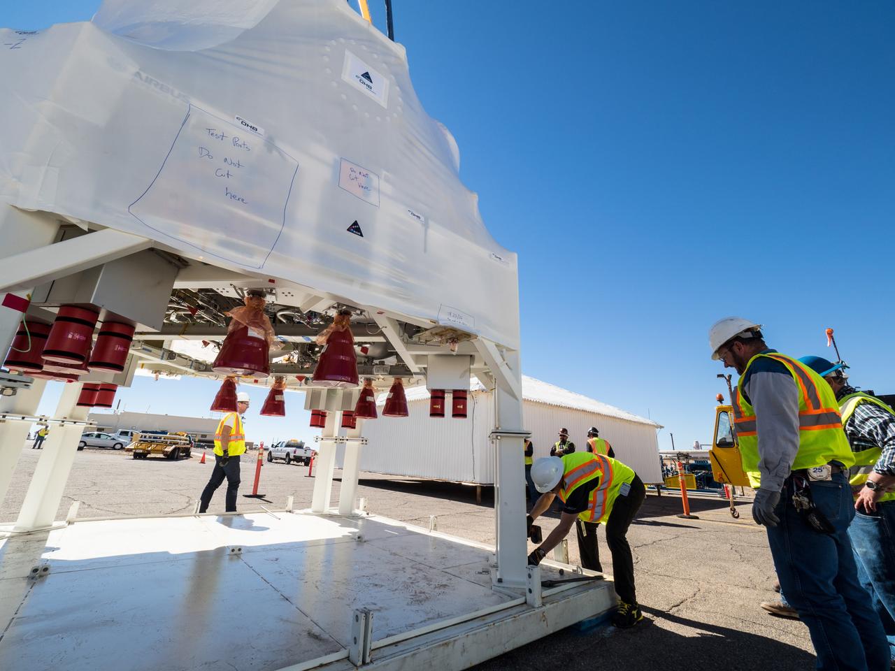
Teams from NASA and ESA completed 48 hot fire tests and three discrete pressurization tests conducted in two phases at White Sands. The focus of these firing tests was the interaction between the engines and the propulsion subsystem, as well as the performance of the pressurization control assembly. Engineers conducted five additional hot fire tests with the auxiliary engines on the PQM, as well as tests on the pressure control assembly valves that involved chilling the valves and performing multiple cycles to recreate anomalies.
Teams successfully conducted a 12-minute propulsion test fire to simulate an abort-to-orbit scenario in which the spacecraft’s service module must place Orion in a safe orbit if a problem were to arise after the LAS has been jettisoned. The test, which was the longest-ever continuous burn conducted on an OMS engine to date at White Sands, used the PQM to fire the OMS engine, eight auxiliary thrusters, and six reaction control system thrusters.
Structural Testing
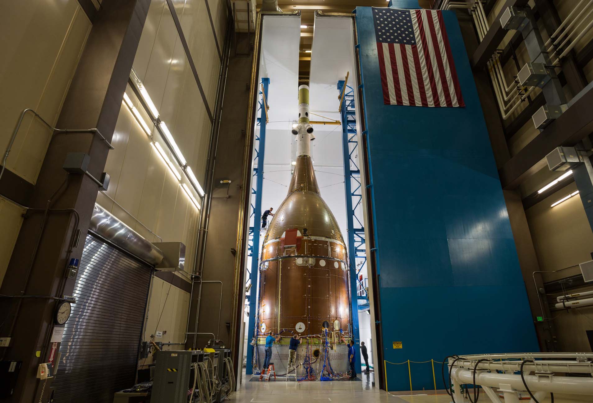
Testing with Orion’s “structural twin” at Lockheed Martin’s facility in Colorado validated Orion’s structure and enabled engineers to push the structure past design standards, simulating the harsh environments that will physically affect the Orion spacecraft. NASA and Lockheed Martin built the structural test article to be identical to Orion’s main structural elements: the crew module, service module, and LAS. It did not include the non-structural items, such as the spacecraft computers, propulsion, and seats, for these tests.
Testing involved a series of 21 tests using six different configurations—from a single element to the full stack—and various combinations in between. The different configurations simulated the different flight conditions—such as launch, return to Earth, parachute deployment, and water landing—that Orion will go through during a mission. During some test phases, engineers pushed expected pressures, mechanical loads, vibration, and shock conditions up to 40% beyond the most severe conditions anticipated during the mission, analyzing data to confirm that the spacecraft structures could withstand the extreme environments of space.
These tests helped to verify Orion’s design and structural durability for Artemis missions to the Moon.
- Pressure Testing: Pushing and pulling with pressure that equates to 140% of the maximum expected loads during missions ensured that the spacecraft structures could withstand intense loads at launch and reentry.
- Modal Testing: During modal testing, dynamic loads of pressure were applied to the spacecraft structures. With more than 20,000 parts making up Orion’s service module alone, modal tests evaluated how the spacecraft components held up to vibration, especially at connection points.
- Stiffness Testing: Stiffness testing applied pressure steadily and continuously to the spacecraft’s structures. This tested how the structures would respond to the static loads that the spacecraft will experience on missions.
- Acoustic Testing: Acoustic testing blasted the structures with sound waves that simulated the vibrating rumble of launch, reaching more than 160 decibels.
- Pyrotechnic Shock Testing: Shock tests recreated the powerful pyrotechnic blasts needed for separation events during flight, such as the LAS separating from the crew module after a successful launch.
- Jettison Testing: Jettison tests mimicked deployment mechanisms required to jettison the forward bay cover and ensured that components could endure the shock levels expected during flight.
- Lightning Testing: Lightning tests evaluated potential flight hardware damage that could occur if the rocket and spacecraft are exposed to a lightning strike prior to launch.
Structural Test Article (STA) Testing
| Start | End | Config | Test | Component |
| 4/11/17 | 4/14/17 | PP | Proof Pressure | CM |
| 5/27/17 | 9/8/17 | 12A | Stiffness/Qual | CM |
| 7/10/17 | 8/21/17 | 6 | Stiffness/Qual | LAS |
| 8/23/17 | 9/1/17 | 10 | Modal | ESM |
| 1/15/18 | 1/21/18 | 9 | Modal | CM/ESM |
| 1/26/18 | 1/30/18 | 3 | Modal | LAS/CM/ESM |
| 6/11/18 | 6/14/18 | 13 | Acoustic | LAS/CM/ESM |
| 6/21/18 | 7/11/18 | 4 | Modal | LAS/CM/ESM |
| 7/24/18 | 7/24/18 | 15 | Pyro Shock | LAS/CM R&R |
| 8/14/18 | 8/15/18 | 18A | Pressure | CM |
| 10/29/18 | 11/16/18 | 5 | Stiffness | LAS/CM/ESM |
| 1/15/19 | 1/31/19 | 18 | Acoustic | CM (FBC GAP) |
| 5/1/19 | 5/1/19 | 19 | Jettison | CM (FBC) |
| 6/3/19 | 9/13/19 | 7 | Stiffness/Qual | ESM |
| 6/8/19 | 7/3/19 | 20 | Pyro Shock | CM (Mortar/Riser) |
| 9/11/19 | 12/4/19 | 12 | Stiffness/Qual | CM |
| 1/22/20 | 1/29/20 | 11A | Modal | LAS/CM/ESM |
| 3/26/20 | 4/13/20 | 14 | Lightning | LAS/CM/ESM |
| 6/1/20 | 6/1/20 | 16 | Jettison | CM/ESM (SAJ) |
| 6/17/20 | 6/17/20 | 17 | Pyro Shock | CM/ESM R&R |
| 7/31/20 | 10/9/20 | 6A | Stiffness/Qual & Modal | LAS |
| 7/15/20 | 7/28/20 | 21 | Pyro Shock | CM (DMJS) |
Aerodynamic, Aerothermal, and Aeroacoustics Testing
Engineers used wind tunnel testing and simulations to understand Orion’s flight behavior in Earth’s atmosphere and develop the aerodynamic, aerothermal, and aeroacoustics databases for Orion. The databases help to verify the performance, controllability, thermal protection system, structure, and safety during all phases of atmospheric flight, including launch aborts, by allowing accurate flight simulations and informing the design for the spacecraft.
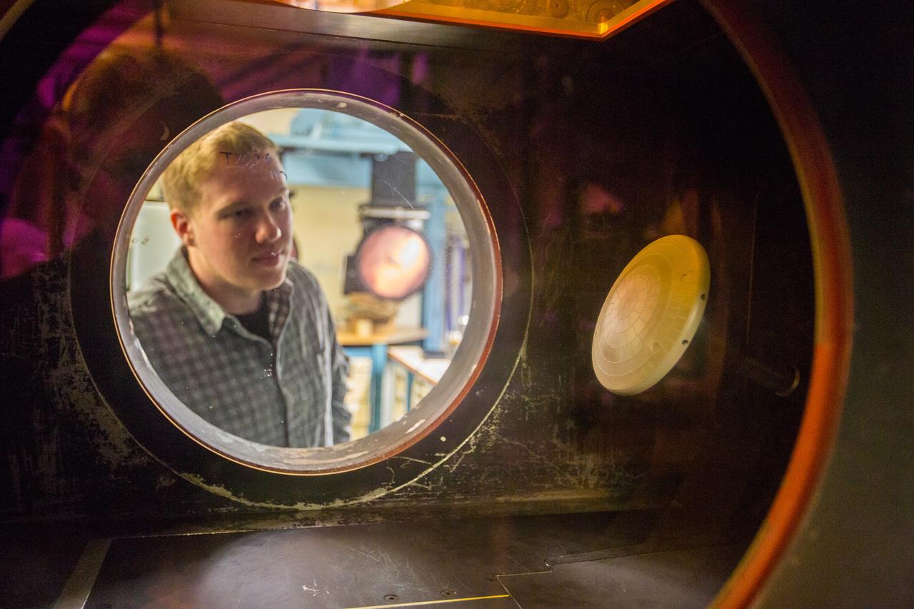
Defining the crew module aerodynamics, both static and dynamic, helped to ensure stable and controllable flight from entry into Earth’s atmosphere to parachute deployment and descent. Similarly, defining the aerodynamics for the LAS helped to ensure successful launch aborts during ascent from the launch pad to orbit. Defining the aerothermal environments for the crew module and LAS ensured that the thermal protection systems will protect them from heat during atmospheric entry, ascent, and ascent aborts. Characterizing the aeroacoustics was also important in designing and testing the Orion and LAS structures for the vibrations and loads they will experience during ascent and reentry.
Teams completed more than 120 tests as part of developing the aerodynamic, aerothermal, and aeroacoustic databases for Orion. Teams have conducted tests in 25 different wind tunnels, four ballistic ranges, two shock tunnels, and three research laboratories across the United States at NASA facilities in Virginia, California, and Ohio; Department of Defense facilities in Tennessee, Maryland, and Florida; and universities such as the University of Buffalo in New York. The tests have covered speeds from 38 mph to about 15,000 mph.
Wind Tunnel Testing
| Test Number | Type | Date | Facility | Description |
| 50-AS | Ascent Acoustics | 5/17/07 | Boeing Polysonic Wind Tunnel (PSWT) | A preliminary investigation into the aeroacoustic loads generated by the Pad Abort Test (PA-1) LAV configuration and the potential reduction in those loads provided by an alternate Launch Abort System configuration (ALAS-2 mod-1) developed by the ALAS project of the NESC. |
| 58-AA | Ascent Acoustics | 10/8/07 | Arnold Engineering and Development Center (AEDC) 4T | Test to identify LAV configuration to adopt for flight. Downselect between ALAS-11 rev 3, rev 8, and rev 10. Approximately12 flush mounted microphones |
| 57-AS | Ascent Acoustics | 11/1/07 | NASA Glenn Research Center (GRC) 8×6 | LAV Ascent Aeroacoustics comparing PA-1 and ALAS-11 rev. 3 configurations with approximately 100 surface mounted microphones |
| 11-CD | Dynamic Stability | 04/8/06 | US Army Aberdeen Test Range | Proof of concept test to evaluate the Aberdeen Research Laboratory telemetry technique for ballistic range test data acquisition and analysis of CM flight. |
| 8-CD | Dynamic Stability | 05/10/06 | NASA Langley Research Center (LaRC) Transonic Dynamics Tunnel (TDT) | Small-amplitude forced oscillation test of CM w/ some unsteady pressures. |
| 12-CD | Dynamic Stability | 06/19/06 | US Army Aberdeen Test Range | Evaluation of improved sabot designs for CM testing at the Aberdeen Test Range |
| 13-CD | Dynamic Stability | 07/6/06 | US Air Force Eglin Ballistic Range | Transonic and supersonic dynamic aero data for zero L/D CM model |
| 15-CD | Dynamic Stability | 09/2/06 | US Army Aberdeen Test Range | Lifting and non-lifting CM models for dynamic aero database development |
| 14-CD | Dynamic Stability | 10/5/06 | NASA Ames Research Center Hypersonic (ARC) Free-Flight Aerodynamics Facility | Transonic and supersonic dynamic aero data of CM at non-zero L/D |
| 18-CD | Dynamic Stability | 01/1/07 | LaRC TDT | Demonstration of Oscillating Turn Table test technique in the TDT to obtain dynamic stability of the CM at high Reynolds numbers. Comparisons with ballistic range data and previous small amplitude forced oscillation test (8-CD) |
| 48-CD | Dynamic Stability | 03/1/07 | LaRC Vertical Spin Tunnel (VST) | Free-flight test of CM at low Mach number to provide dynamic stability estimates for the Pad Abort flight test. |
| 52-CD | Dynamic Stability | 03/1/07 | ARC Fluid Mechanics Laboratory Test Cell 2 (TC-2) | Test technique development to examine issues related to Free-to-Oscillate testing. Will duplicate the conditions of 48-CD test of the CM. |
| 45-AD | Dynamic Stability | 03/9/07 | LaRC VST | Low-Mach number test of LAV in support of PA-1 Flight Test |
| 29-CD | Dynamic Stability | 06/1/07 | ARC Gun Development Facility | Phase 2 of CM dynamic stability at large angles of attack. |
| 82-AD | Dynamic Stability | 12/21/07 | LaRC VST | Forced Oscillation test of LAV in the Vertical Spin Tunnel |
| 27-AD | Dynamic Stability | 03/21/08 | LaRC TDT | Forced oscillation (subsonic and transonic) test of LAV and CM through as much of the 0-180 deg. range as possible |
| 108-CD | Dynamic Stability | 08/25/09 | Bihrle Research VST | Low-speed dynamic stability test to support Orion decisions on back shell angle changes. |
| 109-CD | Dynamic Stability | 11/15/09 | 09 LaRC VST | Dynamic stability of CM under parachutes. |
| 117-CD | Dynamic Stability | 04/1/10 | LaRC VST | Phase 2 of dynamic stability test of CM under parachute |
| 46-AD | Dynamic Stability | 06/1/10 | US Air Force Eglin Ballistic Range | Ballistic range test of LAV. |
| 55-AS | Plume Acoustics | 09/28/07 | Florida State Jet Noise Laboratory | Series of hot- versus cold-jet acoustic experiments to possibility develop scaling laws to allow the use of cold plume tests for the LAV with AM firing. Phase 1 – 2″ 2,000°F jet versus 2″ cold jet. Phase 2 – Same 2 jets with more measurement locations. Phase 3 – ~1″ D nozzle exit hybrid rocket. Phase 4 – Sounding rocket motor plume noise measurements at NASA Wallops Flight Facility. |
| 51-AS | Plume Acoustics | 10/30/10 | ARC Unitary Plan Wind Tunnel (UPWT) | 6%-scale LAV model test to determine the aeroacoustic loading generated by cold air simulation of the AM plumes. ~200 flush microphones. |
| 80-AS | Plume Acoustics | 09/20/10 | ARC UPWT | Hot Helium simulation of AM plumes for acoustic loads. ~200 flush microphones. |
| 53-AA | Plume Jet Interaction (JI) | 05/21/07 | Texas A&M 7×10 Foot Wind Tunnel | First test of subsonic interactions between the ACM plumes and the LAV. Primarily to validate CFD and to provide some data on coast-phase ACM increments for the PA-1 flight test aero database. |
| 16-AA | Plume JI | 06/22/07 | ARC UPWT | Abort loads on the CM due to AM plume JI and proximity to Service Module |
| 59-AA | Plume JI | 09/14/07 | ARC UPWT | High fidelity ACM JI for both Pad Abort-1 flight test article and production ALAS-11rev3B configuration. |
| 60-AA | Plume JI | 01/30/08 | ARC UPWT | Preliminary separation aerodynamics during abort initiation on PA-1 and ALAS-11 rev3B configurations. Preliminary aeroacoustics for nominal ascent (with SM) and abort (LAV only) with cold air plume simulation. |
| 85-AA | Plume JI | 08/20/08 | GRC Aero-Acoustic Propulsion Laboratory | CFD validation test documenting flowfield associated with single AM nozzle at M < 0.3 using PIV. Nozzle at 0°, 25°, and 40° relative to free stream. With and without simplified LAV model. |
| 61-AA | Plume JI | 12/1/08 | LaRC 14- by 22 Foot Wind Tunnel | Subsonic 6%-scale Jettison Motor Jet Interaction test around alpha = 180°. |
| 24-AA | Plume JI | 06/25/09 | AEDC 16T | Transonic/supersonic test of Jettison Motor Jet Interation for LAS jettison during a launch abort (i.e. heat shield forward). |
| 75-AA | Plume JI | 07/24/09 | ARC UPWT | Subsonic, transonic, and low-supersonic ACM Jet Interaction test. |
| 76-AA | Plume JI | 11/24/10 | LaRC UPWT | Supersonic ACM Jet Interaction test (M 1.6 to 4.6). |
| 25-AA | Plume JI | 02/26/10 | ARC UPWT | Supersonic (M 1.6 to 2.5) Jettison Motor Jet Interaction and Jettison LAS/CM Proximity aerodynamics. |
| 26-AA | Plume JI | 08/09/10 | ARC UPWT | Subsonic, transonic, and supersonic AM and ACM Jet Interactions including separation effects data for the LAV. PSP to document pressure loadings during launch aborts. |
| 3-CA | CM Static Aero | 02/10/06 | LaRC UPWT | Study of BL trip techniques on 3%-scale CM model. |
| 7-CA | CM Static Aero | 03/10/06 | LaRC UPWT | Force and moment measurements & pressure distributions, with apex cover on/off and boundary layer transition/tripping study. |
| 5-CA | CM Static Aero | 03/22/06 | ARC UPWT | Force & moments and pressure data on 7.5%- and 3%-scale models. Provided tunnel-to-tunnel comparisons between LaRC and ARC UPWT. |
| 9-CA | CM Static Aero | 04/20/06 | LaRC Mach 6 Tunnel | 3%-scale CM test for alpha from 0 to 180°. |
| 1-CA | CM Static Aero | 12/08/06 | LaRC UPWT | Boundary layer transition measurements with IR thermography and Temperature Sensitive Paint. |
| 19-AA | LAV Static Aero | 01/29/07 | Boeing PSWT | 3%-scale transonic test of PA-1 LAV configuration for 0-180° angle of attack. |
| 54-AA | LAV Static Aero | 04/13/07 | Lockheed High-Speed Wind Tunnel | Quantify the roll coupling with angle of attack caused by the clocking of the abort motor nozzles on the PA-1 configuration. Study effective-ness of various nozzle fairings in relieving the roll interaction |
| 88-AA | LAV Static Aero | 10/20/10 | LaRC VST | Test of the PA-1 Launch Abort Tower alone to define the postjettison aerodynamics. |
| 83-AA | LAV Static Aero | 06/1/08 | LaRC National Transonic Facility | High-Re effects on unpowered LAV aerodynamics. |
| 122-PA | Static Aero | 11/8/10 | ARC TC-2 | Small-scale test of Forward Bay Cover aerodynamics to validate CFD and engineering models of the FBC jettison event. |
Parachutes
NASA has fully qualified the parachute system for flights with crew through an extensive series of 17 developmental tests and eight qualification tests at the U.S. Army’s Yuma Proving Ground in Arizona.
During the development series, engineers tested different types of failure scenarios and extreme descent conditions to refine Orion’s parachute design and ensure that the parachutes will work in a variety of circumstances.
During the qualification testing, engineers evaluated the performance of the parachute system during normal landing sequences as well as several failure scenarios and a variety of potential aerodynamic conditions to ensure that astronauts can return safely from deep space missions.
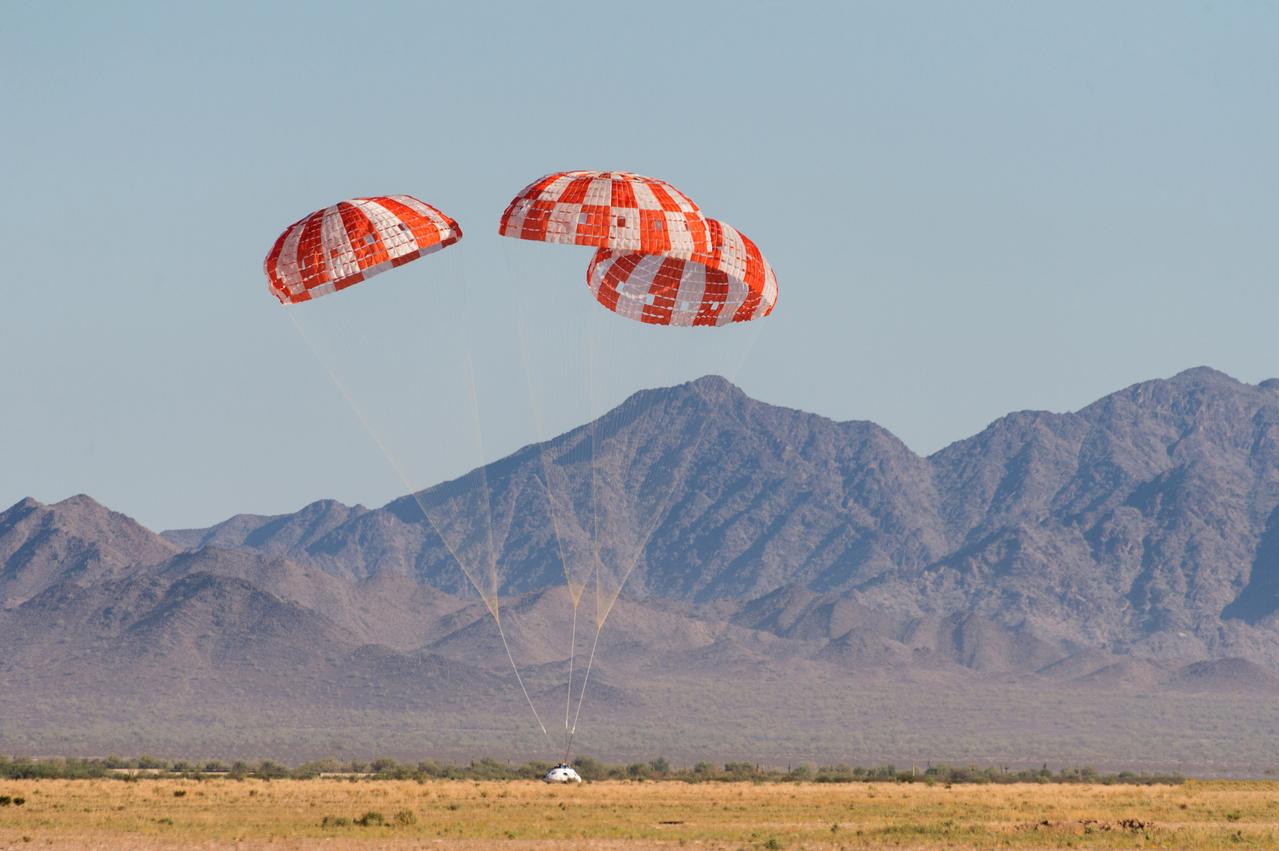
While airdrop testing was a vital, and very visible, component to the development of Orion’s parachutes, ground testing and analysis were equally important to ensuring success. Airdrop testing cannot physically reach all possible spaceflight deployment conditions, but its data helped generate computer models of parachute performance and allowed the team to evaluate the parachutes in altitude and airspeed regimes that could not be thoroughly drop tested. Repeated simulation of the parachutes with varied parameters, called the Monte Carlo method, allowed the team to estimate the bounds of what parachute loads and performance should be expected throughout the life of the program. Ground testing of material capabilities, coupled with the parachute simulations, determined how much structural margin exists in the system. This combination of ground tests, airdrop tests, and analysis qualified the system for Artemis flights with astronauts.
Parachute Engineering Development Drop Testing
| Number | Date | Vehicle | Alt. | FBC | Drogue | Pilot | Main | Primary Test Objective(s) |
| CDT 3-1 | 09/21/11 | PCDTV | 25 kft | – | 2 | 3 | 2 | Nominal system |
| CDT 3-2 | 12/20/11 | PCDTV | 25 kft | – | 2 | 2 | 3 | Drogue skip 2nd, Pilot & Main fail to deploy |
| CDT 3-3 | 02/29/12 | PTV | 25 kft | – | 2 | 3 | 3 | Nominal system with flight-like wake behind PTV |
| CDT 3-4 | 04/17/12 | PCDTV | 25 kft | – | 2 | 3 | 3 | High Q Drogue deploy, Main skip 2nd |
| CDT 3-5 | 07/18/12 | PTV | 25 kft | – | 2 | 3 | 3 | Main skip 1st |
| CDT 3-6 | 08/28/12 | PCDTV | 25 kft | – | 2 | 3 | 3 | Max Q Drogue deploy |
| CDT 3-7 | 12/20/12 | PTV | 25 kft | – | 1 | 3 | 3 | Drogue fail |
| CDT 3-8 | 02/12/13 | PCDTV | 25 kft | 3 | 2 | 3 | 3 | High Q Drogue Deploy, Drogue skip 1st, flagging Main |
| CDT 3-9 | 05/01/13 | PTV | 25 kft | – | 1 | 3 | 3 | Drogue fail, Main skip 1st |
| CDT 3-10 | 07/24/13 | PTV | 35 kft | – | 2 | 3 | 3 | Main skip 1st & released |
| CDT 3-11 | 01/16/14 | PTV | 25 kft | 3 | 2 | 3 | 3 | FBC & nominal system |
| CDT 3-12 | 02/26/14 | PCDTV | 35 kft | 3 | 2 | 2 | 2 | Max Q Drogue deploy, Pilot & Main fail |
| CDT 3-13 | 04/23/14 | PTV | 13 kft | – | – | 3 | 3 | Straight to Mains deploy |
| CDT 3-14 | 06/25/14 | PTV | 35 kft | 3 | 2 | 3 | 3 | FBC & Main skip 2nd |
| CDT 3-15 | 12/18/14 | PTV | 25 kft | – | 2 | 2 | 2 | Textile risers, Main design changes |
| CDT 3-16 | 08/26/15 | PTV | 35 kft | 2 | 1 | 2 | 2 | Minimum System, textile risers, 85% PRL |
| CDT 3-17 | 01/13/16 | PCDTV | 30 kft | 2 | 2 | 3 | 3 | High Q Drogue and Main deploy |
Parachute Qualification Drop Testing
| Number | Date | Vehicle | Alt. | FBC | Drogue | Pilot | Main | Primary Test Objective(s) |
| CQT 4-1 | 09/30/16 | PCDTV | 35 kft | 2 | 2 | 3 | 3 | Two FBCP, nominal system, bounding high Q Drogue and Main deploys |
| CQT 4-2 | 03/8/17 | PTV | 25 kft | – | 2 | 3 | 3 | No FBCPs, min Q Drogue deploy |
| CQT 4-3 | 06/14/17 | PTV | 25 kft | – | – | 3 | 3 | Straight to Mains, low Q deploy |
| CQT 4-4 | 09/13/17 | PTV | 25 kft | – | – | 3 | 3 | Straight to Mains, high Q deploy |
| CQT 4-5 | 12/15/17 | PTV | 35 kft | 2 | 2 | 2 | 2 | Two FBCPs, two Mains |
| CQT 4-6 | 03/16/18 | PTV | 35 kft | 2 | 2 | 3 | 3 | Nominal system with FBC |
| CQT 4-7 | 07/12/18 | PCDTV | 35 kft | 2 | 2 | 2 | 2 | Two Pilots/Mains, high Q Drogue and Main deploy |
| CQT 4-8 | 09/13/18 | PTV | 35 kft | 3 | 2 | 3 | 3 | Nominal system with FBC |
Crew Module Uprighting System Testing
Engineers tested the crew module uprighting system, or CMUS, as part of Orion’s first flight test and implemented a series of design changes to improve its performance. During EFT-1, three of the system’s five bags did not properly inflate. The spacecraft landed and remained upright in the water; however, had the capsule landed upside down, the two functioning CMUS bags would likely not have been able to fully upright the capsule. Design improvements included thickening the inner bladder of each bag to make it more durable, changing how the bags are packed, developing a hard enclosure for the packed bags, and improving manufacturing processes for better control and consistency. During the Artemis I mission, all five CMUS bags deployed after Orion’s splashdown in the Pacific Ocean, demonstrating the successful implementation of the post-EFT-1 changes to the uprighting bags.
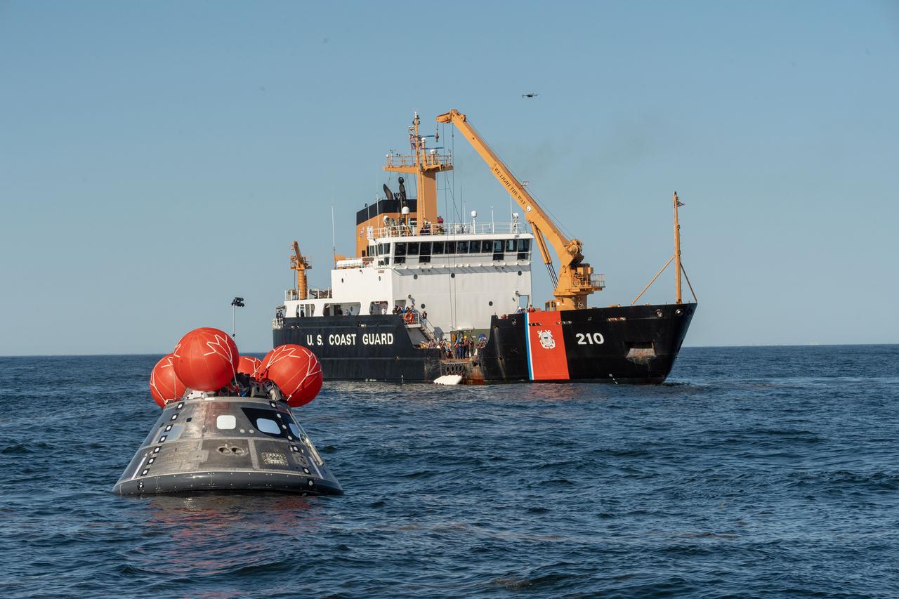
Several full-scale uprighting tests have been performed with a mock-up of the Orion crew capsule, demonstrating that the CMUS would still be able to perform as intended if any one of the five uprighting bags were to fail. This included seven tests in the calm water of the Neutral Buoyancy Lab (NBL) at NASA’s Johnson Space Center in Houston. The Johnson CMUS and NBL teams also successfully completed two tests off the coast of Galveston, Texas, in cooperation the U.S. Coast Guard Cutter Cypress, Air Force personnel, and Texas A&M Galveston. Teams completed an additional four tests in the Atlantic Ocean, off the coast of Atlantic Beach, North Carolina, in cooperation with the U.S. Coast Guard Station Fort Macon and the U.S. Coast Guard Cutter Maple. These tests demonstrated performance in a natural wave environment and were instrumental in the certification of the CMUS.
Water Impact Testing
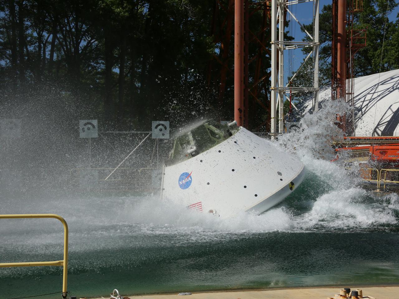
Teams conducted water-impact testing at NASA’s Langley Research Center in the center’s Hydro Impact Basin at the Landing and Impact Research Facility to provide high-fidelity data of the forces that the Orion spacecraft structure and its astronaut crew would experience during landing, helping to protect the crew and informing future designs. Water-impact testing evaluates how the spacecraft may behave in parachute-assisted landings in different wind conditions and wave heights.
Engineers used three different test versions of Orion as the spacecraft’s design was refined over the course of the test series. The final series of drop tests used the test article previously used for structural testing at Lockheed Martin’s facility in Colorado, which was based on the final design for the configuration that will fly on Artemis II. Teams used data from the drop tests as well as from the Artemis I mission in final computer modeling for loads and structures prior to Artemis II.
STORRM – Sensor Test for Orion Relative Navigation Risk Mitigation
The Sensor Test for Orion Relative Navigation Risk Mitigation (STORRM) was successfully demonstrated on Space Shuttle Endeavour’s STS-134 mission to the International Space Station (ISS) on May 16, 2011. The goal of STORRM was to validate a new relative navigation sensor based on advanced laser and detector technology that will make docking and undocking easier and safer, and to test the hardware in the same environment the sensors would experience on the first Orion rendezvous to another vehicle. Astronauts tested the navigation and docking system during the initial docking approach and again after undocking, including an unprecedented re-rendezvous of the ISS as Commander Mark Kelly and pilot Greg Johnson flew an Orion-like approach before deorbiting on Flight Day 14. Astronaut Andrew Feustel operated the STORRM equipment.
STORRM hardware included a laser-based state-of-the-art vision navigation sensor (VNS), which provided an image of the target and calculated precise accuracies for range, bearing, alignment, and orientation data up to six degrees of freedom. In comparison, the space shuttle’s sensors could only calculate up to three degrees of freedom. The system also included a docking camera for high-resolution color imagery, an avionics assembly with a power distribution unit, data recorder unit, and memory storage that communicated with a space-certified laptop, and five reflective docking targets that had been installed on the space station during STS-131. Working together, these sensors provided real-time 3D images with a resolution 16 times higher than previous shuttle sensors.
STORRM collected 600 gigabytes of data, and the VNS performed better than expected by providing continuous measurements from as far away as 3.5 miles to within six feet of the space station — three times the range capability of the current relative navigation sensor — and producing exceptional 3D images of the target. The data collected by STORRM will help make docking and undocking with other spacecraft safer and easier for astronauts on Orion.
Mission Quick Facts:
| Launch date | May 16, 2011 8:56 a.m. EDT |
| Launch site | Launch Complex 39A, NASA Kennedy Space Center |
| Launch vehicle | Space Shuttle Endeavour |
| Landing site | NASA Kennedy Space Center, Florida |
| Landing date | June 1, 2011 2:34 a.m. EST |
L
Avionics and Software Testing
The Orion program uses a network of integrated test labs designed to reduce cost and schedule risk by providing an early opportunity in the development phase of the program to perform systems-level avionics and software testing for Orion in a realistic environment.
Engineers used Lockheed Martin’s state-of-the-art facility called the Exploration Development Laboratory in Houston for this testing, including avionics system testing to reduce risk prior to the Pad Abort-1 test and Exploration Flight Test-1. Initial testing of systems also included the guidance, navigation, and control, as well as automated rendezvous and docking, and crew interfaces. Engineers also use the facility to perform development, integration, and dry-run testing of Orion avionics hardware and software and associated internal and external crew module interfaces using flight-representative software and an appropriate suite of ground support tools, systems, and software.
Lockheed Martin’s Orion Integrated Test Lab, or ITL, located near Denver, runs full mission scenarios from prelaunch to landing, or specific phases of the flight. The lab uses a full-size Orion mockup with a fully integrated set of Orion’s crew module and service module avionics, power, wiring, guidance, navigation, and control hardware. The lab’s systems connect to the MCC, which allows for real-time monitoring and commanding of the spacecraft in Houston in order to simulate the Artemis II mission.
Tests performed in the ITL are essential for identifying software problems and validating proper functionality and performance of the spacecraft avionics system. An ITL configuration is the highest-fidelity test platform that Orion avionics hardware and software would experience prior to actual testing regimens on the assembled spacecraft, providing as close to a “test like you fly” environment as can be assembled within a lab setting.
Flight Control Team Training and Testing
The flight control team is in the midst of training for the Artemis II mission in and will continue in the weeks prior to launch. As software, hardware, and operations plans are finalized, they refine and practice procedures they will use on the ground to monitor, command, and control Orion. Flight controllers in the MCC prepare by simulating various parts of Orion’s journey, from launch through outbound transit to the Moon, including the trans-lunar injection burn that sends the spacecraft out of Earth orbit and toward the Moon. The MCC also simulates Orion’s lunar flyby and trans-Earth return through entry, descent, landing, and recovery, including the final trajectory corrections and burns Orion will need to enter the atmosphere and splash down in the Pacific Ocean.
The agency began conducting a host of integrated simulations with the crew, launch, and flight control teams in the months before the mission. The crew trains and participates in simulations from the Orion Mission Simulator, a full-task mission trainer at Johnson. The high-fidelity vehicle simulator incorporates real flight software and extensive malfunction capabilities, allowing teams to train on nominal flight activities as well as complex malfunction scenarios including emergency events.
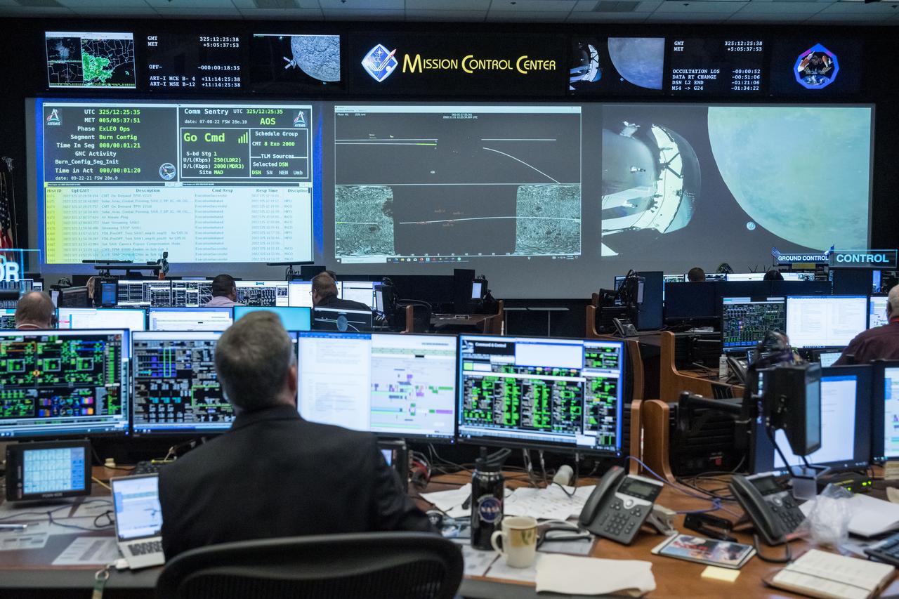
Simulations and testing have also included joint operations between industry partners and NASA’s flight operations team, with NASA doing real-time monitoring and commanding of the simulated version of Orion at the ITL in Denver from the MCC in Houston. Testing and training has also been done with a medium-fidelity mockup to validate spatial requirements, and a low-fidelity Orion mockup at the Exploration Development Lab in Houston. Testing also has been performed with the actual Orion spacecraft while it is at Kennedy Space Center.
Engineers also tested the Orion communications system to ensure that the spacecraft and the MCC could flawlessly communicate and send data through NASA’s satellite networks in space and on the ground. The MCC verified that these communication systems work with Orion during tests of different Artemis II scenarios from launch to landing.
The post Testing appeared first on NASA Science.